A Booxhi Technologies unit
Aerospace Structures Unit
From Design Concept to Certification
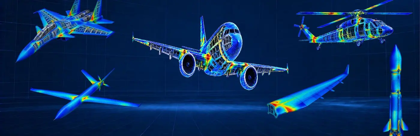
Our core capabilities
One team taking airframe structures from first concept through analysis and test, all the way to airworthiness clearance.
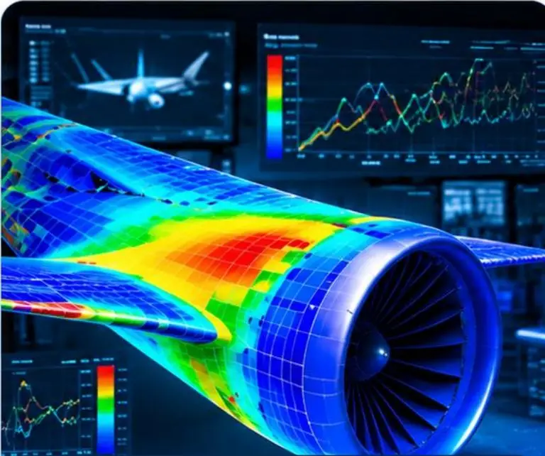
Design & Analysis
CAD / CAE
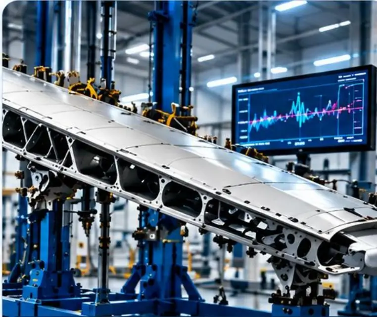
Testing & Validation
GVT, VQT

Certification
CEMILAC, RCMA, DGCA
Finite Element Modelling
Global and component level FE models for fixed wing, rotary wing, UAV and store carriage structures.
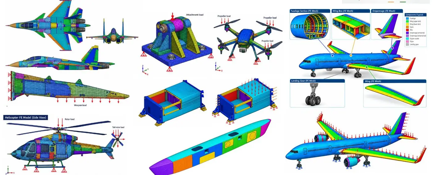
Finite Element Analysis
From static strength to aeroelasticity, we assess and clear structures across the full flight envelope.
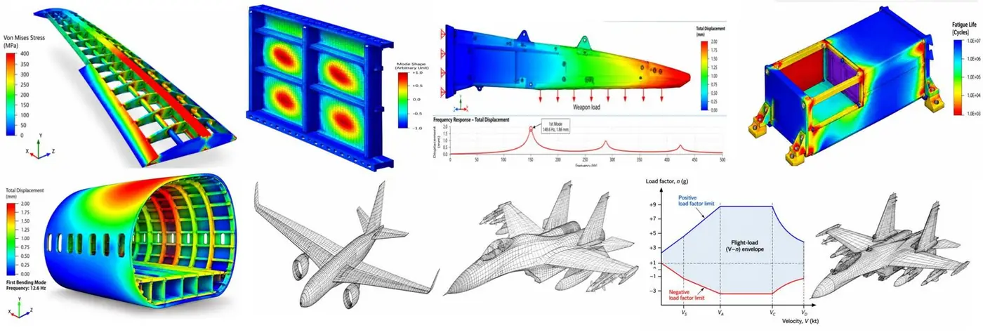
Structural Analysis
- Static analysis
- Buckling analysis
- Modal and dynamic analysis
- Fatigue and durability analysis
Advanced Analysis
- Dynamic response analysis
- Aero-mechanical analysis
- Aeroelastic analysis
- Vibration fatigue analysis
Assessment & Clearance
- Component strength assessment and clearance
- Structural integrity assessment
- Military aircraft upgrade and modification assessment
- First flight structural clearance
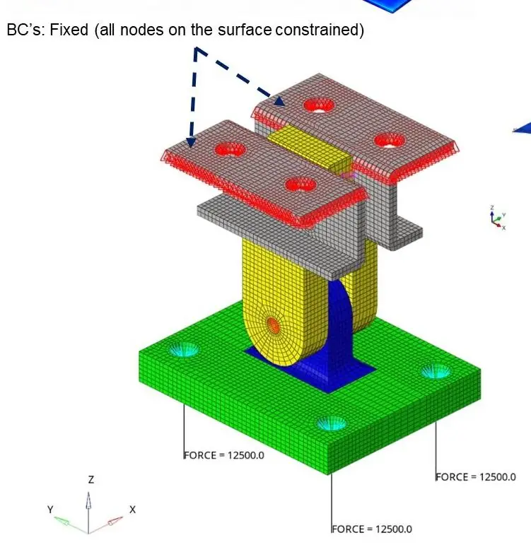
Detailed Finite Element Analysis
Local joints, fasteners, connectors and contact, modelled in the detail certification demands.

| FE domain | Capability | Output |
|---|---|---|
| Joint idealisation | Bolts, rivets, fasteners | Load transfer and joint behaviour |
| Connector idealisation | RBE2, RBE3, CBUSH, CBEAM, CBAR | Stiffness and load distribution |
| Interface modelling | Contact, friction, preload | Interface forces and separation |
| Local FE modelling | Holes, fillets, cut-outs, attachments | Local stress concentration |
| Stress and load path | Bearing, bypass, shear, principal stress | Critical load path and hotspots |
| Structural integrity | Strength, fatigue, durability | Margins of safety, fatigue life, damage |
Ground Vibration Testing
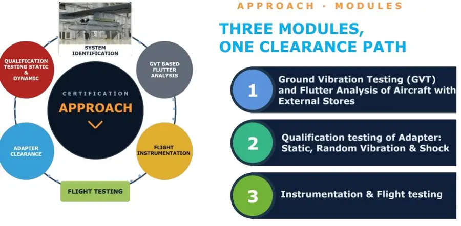
Three modules, one clearance path. GVT and GVT based flutter analysis for aircraft with external stores.
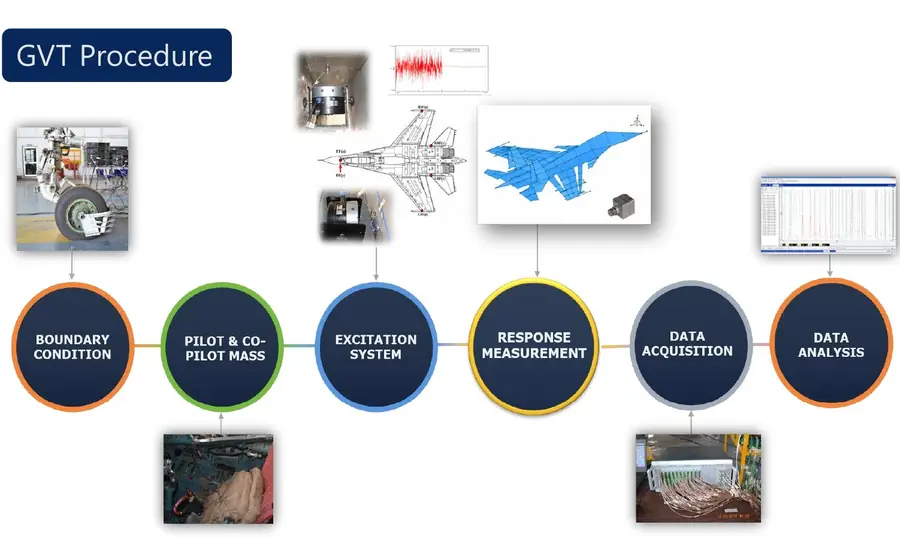
System identification through GVT
Frequencies, mode shapes and damping
Unsteady aerodynamics from NASTRAN
Aerodynamic modelling feeding the flutter solution
GVT based flutter analysis
Using an equivalent FE model tuned to test data
GVT & Flutter Analysis
Aircraft with external stores
Adapter Qualification
Static, random vibration and shock
Flight Instrumentation & Testing
Flight data acquisition and validation
Material Characterisation
We test metallic and composite materials and turn the results into property inputs for FE models.
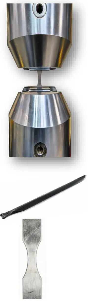
Metallic materials
| Property / test | Scope |
|---|---|
| Static testing | Tensile, compression and shear |
| Fatigue testing | High cycle and low cycle fatigue |
| Tensile properties | UTS, 0.2% proof stress, Young's modulus and elongation |
Composite materials
| Property / test | Scope |
|---|---|
| Materials | Carbon and glass fibre reinforced polymers |
| Lay-up and curing | Wet hand lay-up, prepreg lay-up and curing |
| Fibre orientation | Unidirectional (UD) and bidirectional (BD) |
| Static testing | Tensile, compression and in-plane shear |
| Laminate response | Interlaminar properties and fatigue response |
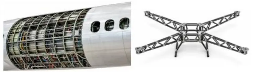
Specimen preparation
Machined to size with tabs attached, edges ground and polished, strain gauged and labelled
Test conditions
Room temperature dry (RTD), elevated temperature dry (ETD) and elevated temperature wet (ETW)
Engineering outputs
Stress strain curves, elastic constants (E, G, ν), static strength, S–N and ε–N fatigue data, and material inputs for FE models
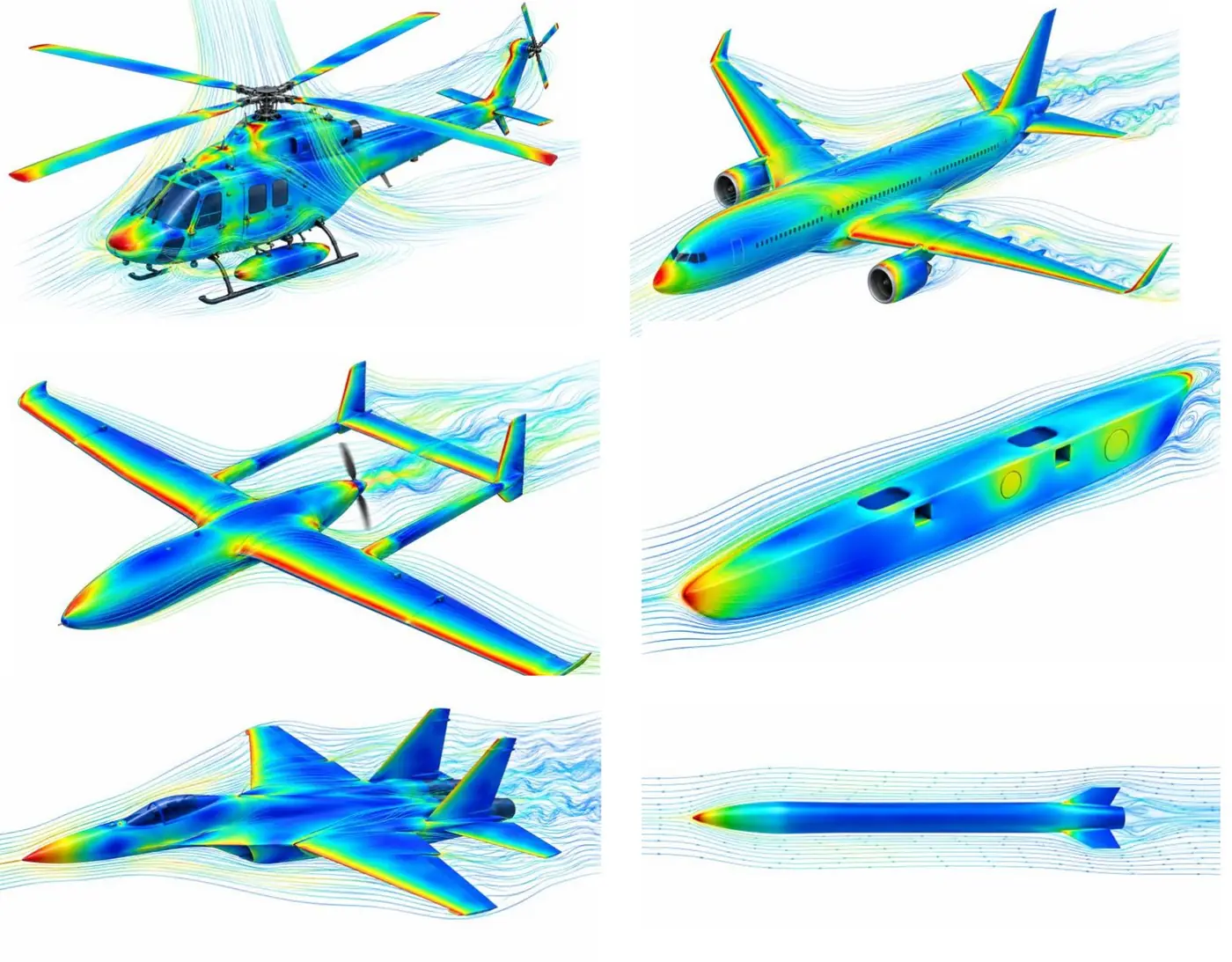
Computational Fluid Dynamics
Flow and load prediction that feeds straight into our structural models.
Let's clear your next structure
Tell us about your airframe, store integration or test campaign and our structures team will get back to you.
Email our team